About the club
The Autonomous Robotics Club (ARC) was founded with the goal of competing in the Intelligent Ground Vehicle Competition (IGVC). It consists of undergraduate students mainly in Electical Engineering and Computer Science. The robot — Taurus — was first entered into IGVC in 2016, where we won the Rookie of the year award. Taurus uses sensors such as GPS, LiDAR and Compass to determine its position in the environment. A list of components is below. Taurus runs on a small laptop that is mounted on the rear, and coded in C++.
Hardware
Sensors
- GPS
- Two cameras
- LIDAR
- Encoders
- Compass
Actuators
- Motors/Motor Controller
Computer & Microcontrollers
- Laptop
- Arduino
Software
Overview
The whole system was implemented in C++, consisting of around 2700 lines of code. The system was running at about 0.6 seconds per iteration of the main loop. Each iteration consisted of collecting data from each sensor, processing the data and outputting a command to the actuators.
Fuzzy Logic
Fuzzy logic is a system of non binary logic. Instead of truth values (true/1 and false/0), statements are assigned a value between 0 and 1 inclusive. This value is called the membership value. It represents the membership of a set or concept. We will call these fuzzy sets. A collection of fuzzy sets form what we will call a fuzzy function. fuzzy logic was used as the motion planner. The controller consisted of three fuzzy function: Near-Far, Target, and Free-Space.
The Fuzzy Sets
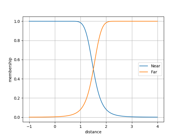
Near-Far
The Near-Far fuzzy funtion is shown below. The input is the distance to the closest obsticle. This value is calculated based on Lidar and camera data. The output is the membership value of both the near and far set. We will denote the membership value for the near and far functions as \(n\) and \(f\) respectively.
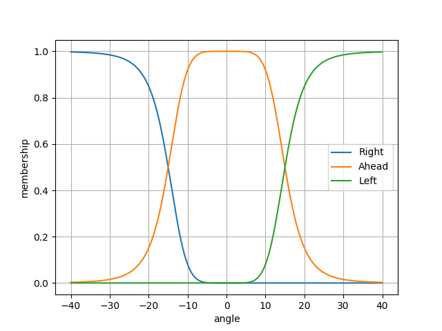
Target
The Target function is shown below. The input is the angle from Taururs’ current heading to the target gps waypoint. This is calcuated from the compass and the current gps location. The output is the membership value of the left, ahead, and right fuzzy sets. We will deonte this as \(t\).
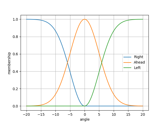
Free-Sapce
The Free-Space function is shown below. The input is the angle from Taurus’ current heading to the “most open area”. How “most open” is determined will be described later. Again the output is the membership to the left, ahead, and right fuzzy sets. We will denote this as \(s\).
Calculating Desired Heading
First we calculate \(lar = n\cdot s + f\cdot t\). This calcuation can be interpreted as: if the closest object is “near” (\(n \approx 1\)) steer to free space, if the closest object is “far” (\(f \approx 1\)) steer to the target. We then compute \(a = lar \cdot [-1, 0, 1]^T\). \(a\) is an unitless abstract steering amount, where \(a \in [-1,1]\). This abstract steering amount is translated to steering commands for the motor controller. The translation is the following: \begin{align} left = b - a\cdot m \end{align} \begin{align} right = b + a\cdot m \end{align} \begin{align} m = b\cdot c \end{align} This leaves two constants to adjust, \(b\) the base speed, and \(c\) a multiplier. From our experiments the best values for these constants are \(b=0.35\) and \(c=0.3\). Note that \(left,right \in [-1, 1]\), they are a percentage forward/backward for the left and right wheels.
Camera
Calibration
The camera took pictures at an angle to the ground, therefore all images need to be transformed to represent accurate distances in laser (real world) space. We used a checkerboard to aid in determining this transformation.
Lane Marking Detection
Taurus used a predetermined filter to filter out grass, in CIE Lab* colour space. The image is then converted to a black and white image where white pixels indicate where the white lines are and everything else is black. The Hough Transform was then used to extract lines from the image. The lines were then transformed from the calibration using a projective transformation in order to convert the points from image space to laser space (world coordinates). These transfomed lines were then used as simulated lidar for easy merging with the lidar data later.
Lane and Obstacle Processing
Lidar was used to detect obstacles on the course; it would provide a 270 degree sweep of the local area. Both lane detection and Lidar produced distance and angle data sets. These two sets were then meshed together by taking the minimum distance from each angle. Edges of objects are extended to account for the width of Taurus, allowing computations to be based on a point mass rather than a rectangle. The extension process closes holes in dashed lines to accommodate for errors in the data. A \(50 \times 75\) binary grid was populated with the merged Lidar data. \(1\) represents free space and \(0\) represents occupied or unknown space (space behind obstacles). The distance transform was then applied to the binary grid. The distance transform replaces every \(1\) with the distance to the nearest \(0\) (\(L_2\) norm). Below is an example result from the distance transform. Blue is low and yellow is high.
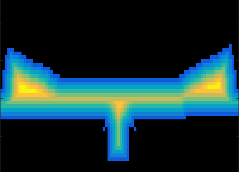
The approximate maximums (near global maximums) were extracted from the distance transform heat map. From these a “best” free space direction was chosen based on angle to the waypoint. This is the input to the Free-Space fuzzy function.
Sample Run
The video below was one of our best runs. The dead end was the hardest part of the course. Since the motors are so far forward, the back of the robot swings while turning.